Mechanical Design
On the mechanical design side, our system needed a stable and level maze plate, precise motors, and a setup for our camera to give ball position feedback. Additionally, we added customizable functionality into the solver code and paired it with removable walls to allow users to create a new maze setup. The system uses a pairing of stepper motors with a crank arm and rc car suspension linkages to tilt the board in two directions. Due to the relatively small angle needed to accelerate the ball, crank-arm-to-board rotation acted in a 1:2 ratio. Individual features of the assembly are described in more detail below.
Materials
-
NI MyRIO | (2) Stepper Motor - 200 step/rev | (2) L298N Motor Driver | Breadboard & wires | Camera - RBG, 32-bit, 640p
-
(2) RC Car Linkages | U-joint | Acrylic & Wood (0.25", 0.125") Laser Cut | ABS & PLA 3D Prints
a
Camera Mast & Maze Plate

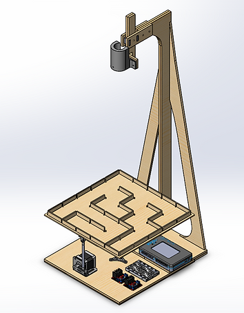
In order to properly track the motion of our ball, a stiff camera mast immune to disturbance was needed. After trying a single beam mast, we ran into issues with table bumps and movements of the motors leading to a shaking camera. This final design was then implemented with stiffening struts that greatly improved camera stillness. On top, a tightening mechanism was added which places the camera on a movable mount to zero in to the optimal height for capturing just the board
Our maze plate went through multiple iterations, as it was the highest precision part of the system. Any warping would ruin fine angle control. Initially 0.125" wood was used but had a noticeable curl that threw off motion, necessitating a switch to flatter acrylic. Once some stiffening struts were added, this issue was corrected. Multiple more iterations were still needed to perfect the fit of the maze walls. Their slots had to be perfectly sized and spaced so as to not interfere with ball motion and to snugly hold the walls without them rattling in place.
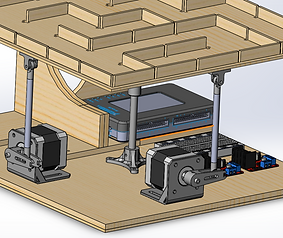
Electronics Mount & Linkages